
 EN
EN
 ar
ar bg
bg hr
hr cs
cs da
da nl
nl fi
fi fr
fr de
de el
el hi
hi it
it ko
ko no
no pl
pl pt
pt ro
ro ru
ru es
es sv
sv tl
tl iw
iw id
id lv
lv lt
lt sr
sr sk
sk sl
sl uk
uk vi
vi et
et hu
hu th
th tr
tr fa
fa ms
ms hy
hy ka
ka ur
ur bn
bn mn
mn ta
ta kk
kk uz
uz ku
ku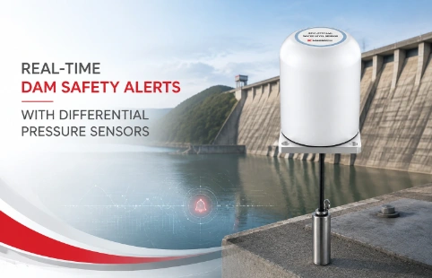
Real-Time Dam Safety Alerts with Differential Pressure Water Level Sensors
Key Takeaways An alert chain needs more than a sensor: define field in...

Hydrostatic Pressure Sensor Level Measurement by Kingmach
When level signals drift and field calibrations don’t stick, the sensor itself is often the weak point. Level measurement sounds straightforward, but real-world conditions—temperature shifts, aggressive media, awkward mounting—quickly expose gaps in sensor design. Kingmach’s hydrostatic pressure sensors are built around these field realities rather than lab benchmarks. Instead of chasing headline accuracy numbers, we focus on what keeps readings stable day after day: vented cables that equalize atmospheric pressure, diaphragm materials matched to your media, and electronics that compensate for thermal drift without constant intervention. Whether you’re monitoring a sewage sump, a deep groundwater borehole, or a fuel storage tank, the same sensing principle applies—hydrostatic head pressure converted into a clean electrical signal. But the difference between a sensor that works on day one and one that works year after year comes down to how it handles the in-between stuff: condensation, corrosives, cable snagging during installation. Over the years, we’ve learned to sweat those details so you don’t have to. This page walks through how our hydrostatic level measurement sensors perform in practice, without the glossy brochure language.
Technical Detail
A hydrostatic pressure sensor measures liquid level by detecting the weight of the fluid column above it—the deeper the sensor sits, the higher the pressure. It’s a simple, reliable principle, but getting a consistent signal means the sensor body, cable, and electronics all need to work as a system. Kingmach builds these sensors with welded 316L stainless steel bodies as standard, with optional Hastelloy or PTFE coatings when the process demands higher chemical resistance. The sensing diaphragm is isolated from the environment by an oil-fill system that transmits pressure while keeping out moisture and sediment. We don’t publish a one-size-fits-all accuracy spec, because a sensor installed in a clean water tank behaves differently from one buried in landfill leachate. Instead, we configure each unit for the expected temperature range and cable length, compensating for thermal zero drift and span drift at the factory. Output options are straightforward: 4–20 mA with HART, or RS485 with Modbus RTU, depending on your control system. The cable is just as important as the housing. We use polyurethane or FEP-jacketed vented cables with a Kevlar strain relief to prevent stretching, because even a tiny change in cable diameter can pinch the vent tube and throw off readings. For deep wells or tanks with turbulence, we add a weighted nose cone and a stainless steel clamp. Users often ask about installation in confined spaces or with solids-heavy fluids. We recommend a stilling well or a protective pipe to shield the sensor from debris and surges. Kingmach’s supply chain covers everything from standard 1-meter range sensors for day tanks to custom 200-meter units for dam monitoring, with lead times that factor in local certification needs. Technical support isn’t a chatbot—when you call, you’ll speak with an engineer who has actually seen the data from a failed installation and can troubleshoot wiring, scaling, or venting issues over a quick call. Our customers range from municipal water authorities in Southeast Asia to mining operations in South America, and the common thread is a need for level data they can trust without babysitting the instrument.
News
Key Takeaways An alert chain needs more than a sensor: define field in...
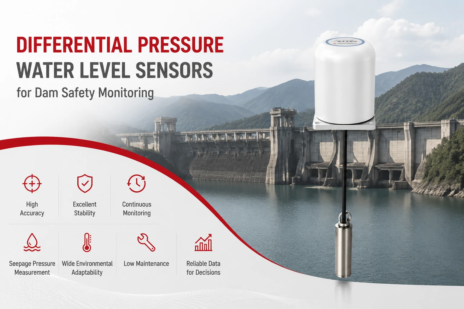
Key Takeaways The strongest fit is usually a confined, submerged, or s...
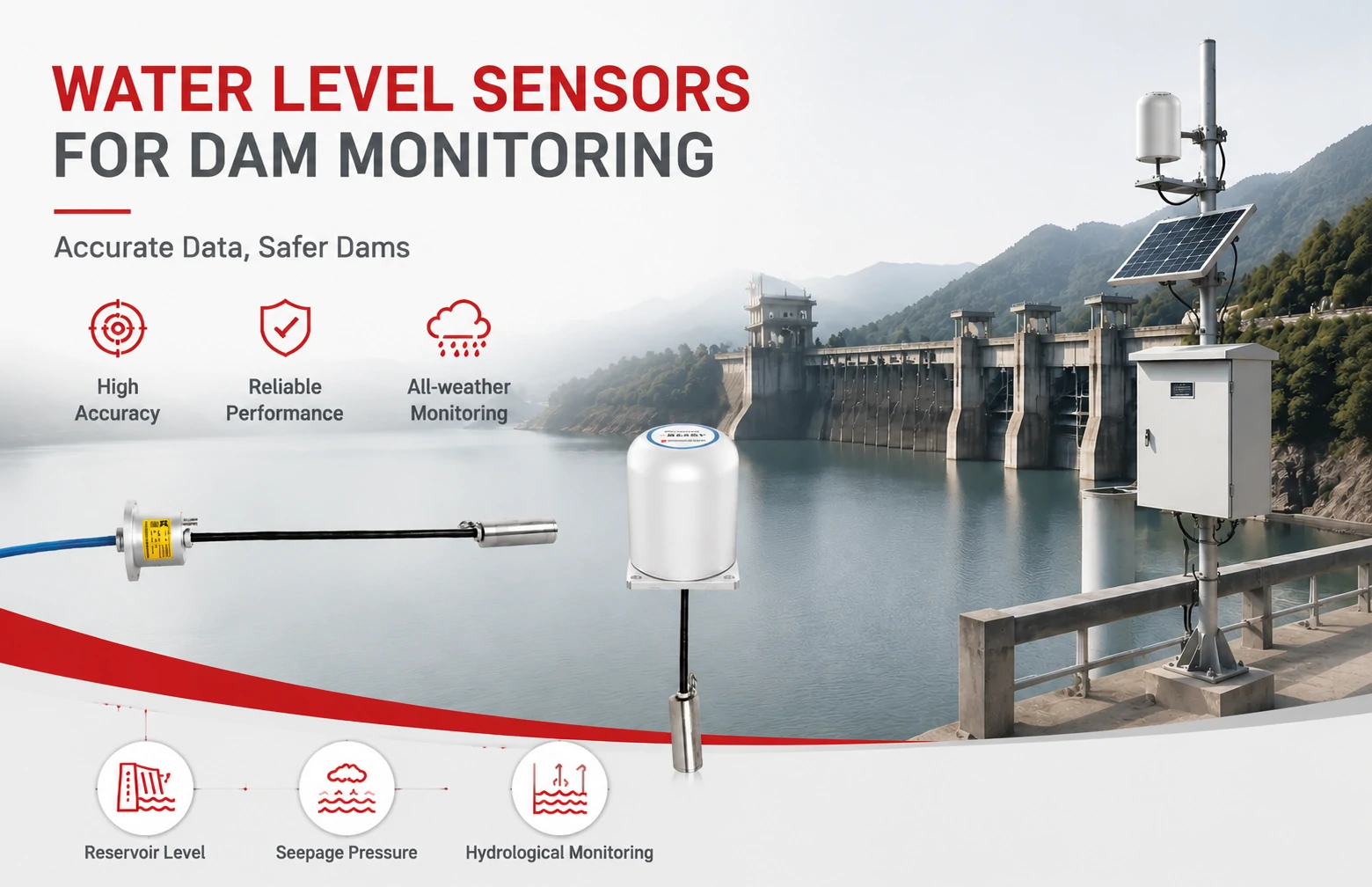
Kingmach Water Level Sensors for Dam Monitoring: A Buyer's Guide to Differential Pre...
Products
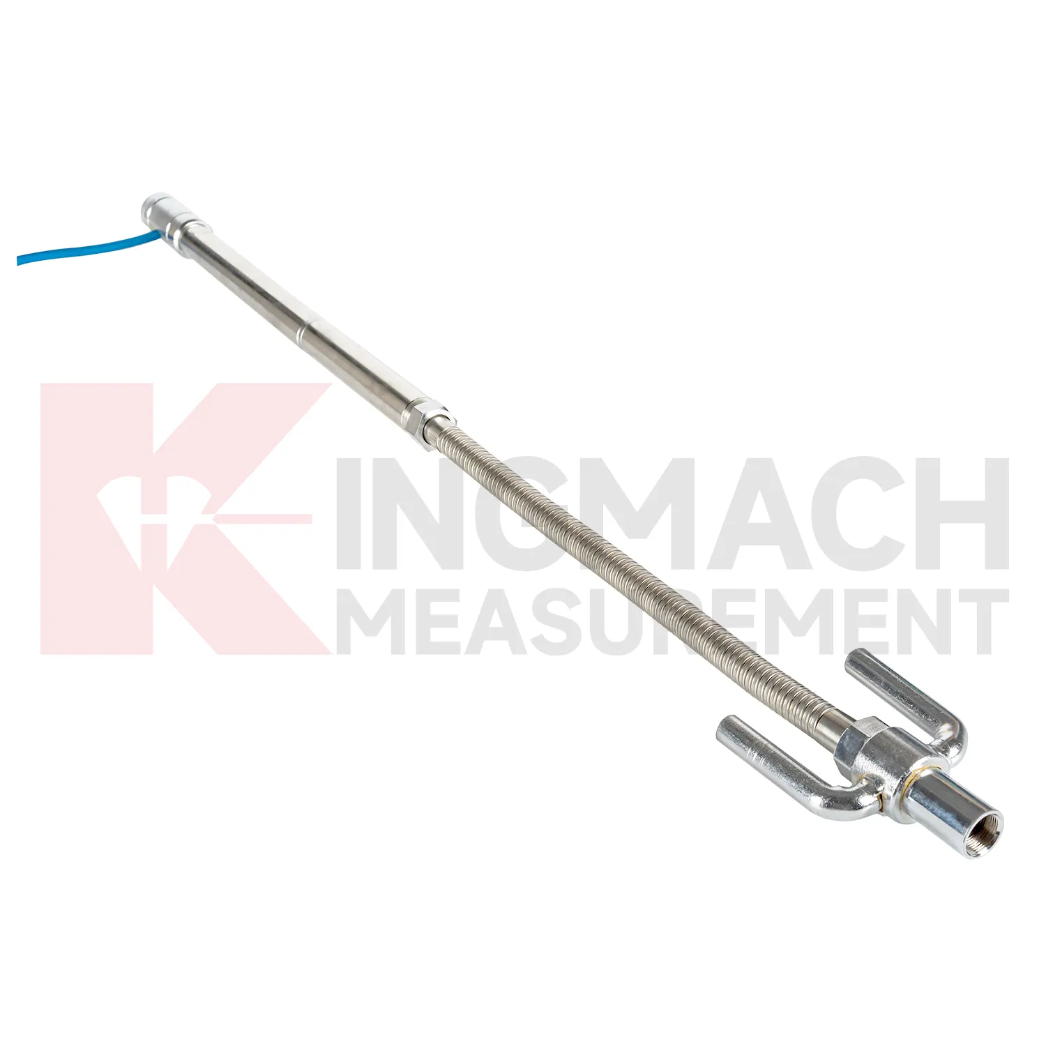
Smart Single-Point Settlement Gauge JMDL-47XXAT
View Details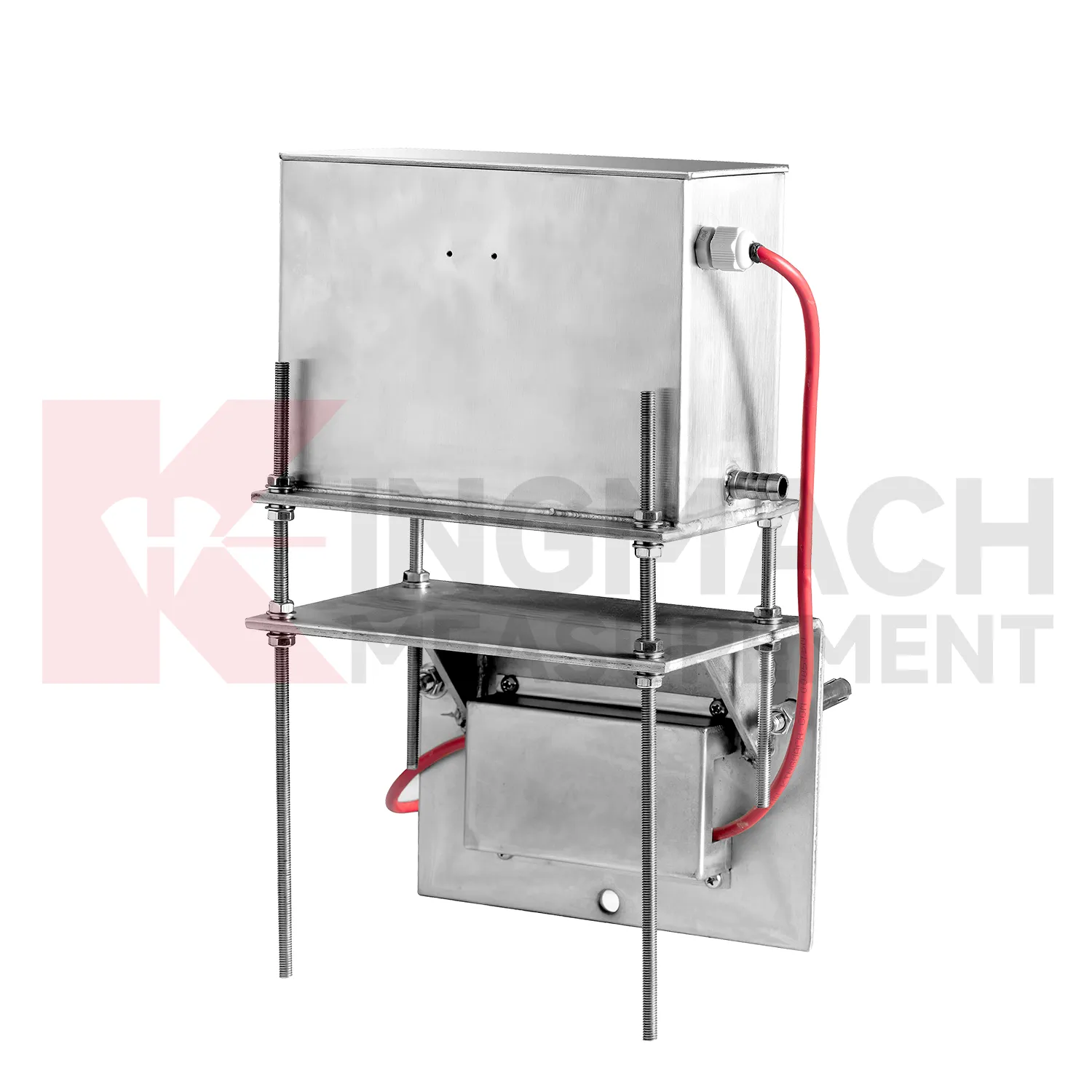
Micro Range Hydrostatic Level Sensor JMQJ-62XXADT
View Details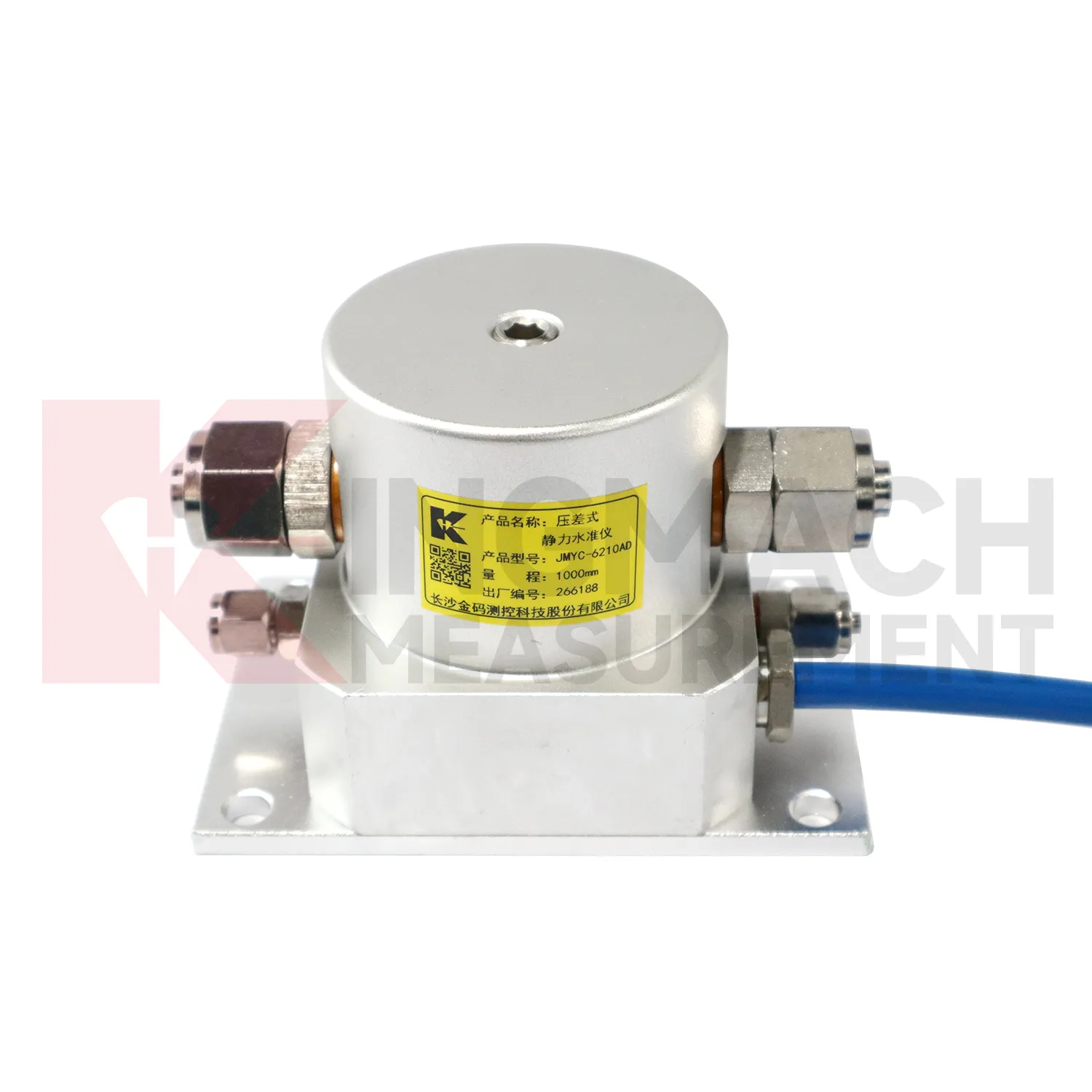
Wide-Range Differential Pressure Hydrostatic Level Sensor JMYC-62XXAD
View DetailsFAQ
Hydrostatic sensors measure pressure at the bottom of the tank and convert it to level based on fluid density. They must be in contact with the liquid. Ultrasonic transmitters measure the time of flight of a sound pulse reflected from the surface—they’re non-contact. Hydrostatic sensors are often preferred when there’s heavy foam, vapor, or dust in the air, because those conditions scatter ultrasonic signals. They also give continuous readings unaffected by surface turbulence if installed in a stilling well.
Standard options are 4–20 mA (two-wire loop powered) with optional HART communication, and RS485 with Modbus RTU protocol. We can also supply voltage outputs (0–5 V, 0–10 V) if your DAQ system requires it. The signal selection depends on cable distance: 4–20 mA handles hundreds of meters without degradation, while RS485 is better for networked installations where you want multiple sensors on a single bus.
Yes, but the material selection is critical. For seawater or brackish water, we typically recommend 316L stainless steel body with a PTFE-jacketed cable. For strong acids or solvents, we move to Hastelloy C-276 or fully PTFE-coated sensors. The cable vent tube also needs a corrosion-resistant design to prevent salt crystal buildup. Tell us the specific media and concentration, and we’ll confirm compatibility from our chemical resistance database.
Drift often comes from three sources: a blocked vent tube in the cable, moisture ingress into the reference side, or thermal cycling that wasn’t fully compensated. Make sure the vent cap is dry and free of dust or insects. Check the cable for kinks or compression that could seal the vent path. If drift persists, the sensor might need a factory recalibration—we can do a bench check and identify whether the issue is a seal failure or an electronics fault.
Usually not, because the sensor is calibrated at the factory for the specified range and temperature limits. However, if the actual fluid density differs significantly from water (1.0 g/cm³), you’ll need to apply a scaling factor in your PLC or controller. For example, in 0.9 g/cm³ oil, a 10-meter column creates only 9 meters of equivalent water pressure, so the raw reading must be divided by 0.9. We provide this density correction formula in the manual, and support can walk you through the setup for Modbus or HART devices.
Share your product type, target capacity, and application requirements. Our team can review the details and recommend a practical next step.
If you are interested in our products or want to become our partner.
Please leave your contact information, our team will contact you as soon as possible.
Mail: [email protected]
Contact Us: +8613808434127
Address: No. 188 Tongzipo West Rd, Changsha, Hunan, China