 ar
ar bg
bg hr
hr cs
cs da
da nl
nl fi
fi fr
fr de
de el
el hi
hi it
it ko
ko no
no pl
pl pt
pt ro
ro ru
ru es
es sv
sv tl
tl iw
iw id
id lv
lv lt
lt sr
sr sk
sk sl
sl uk
uk vi
vi et
et hu
hu th
th tr
tr fa
fa ms
ms hy
hy ka
ka ur
ur bn
bn mn
mn ta
ta kk
kk uz
uz ku
ku
load cell wire diagram
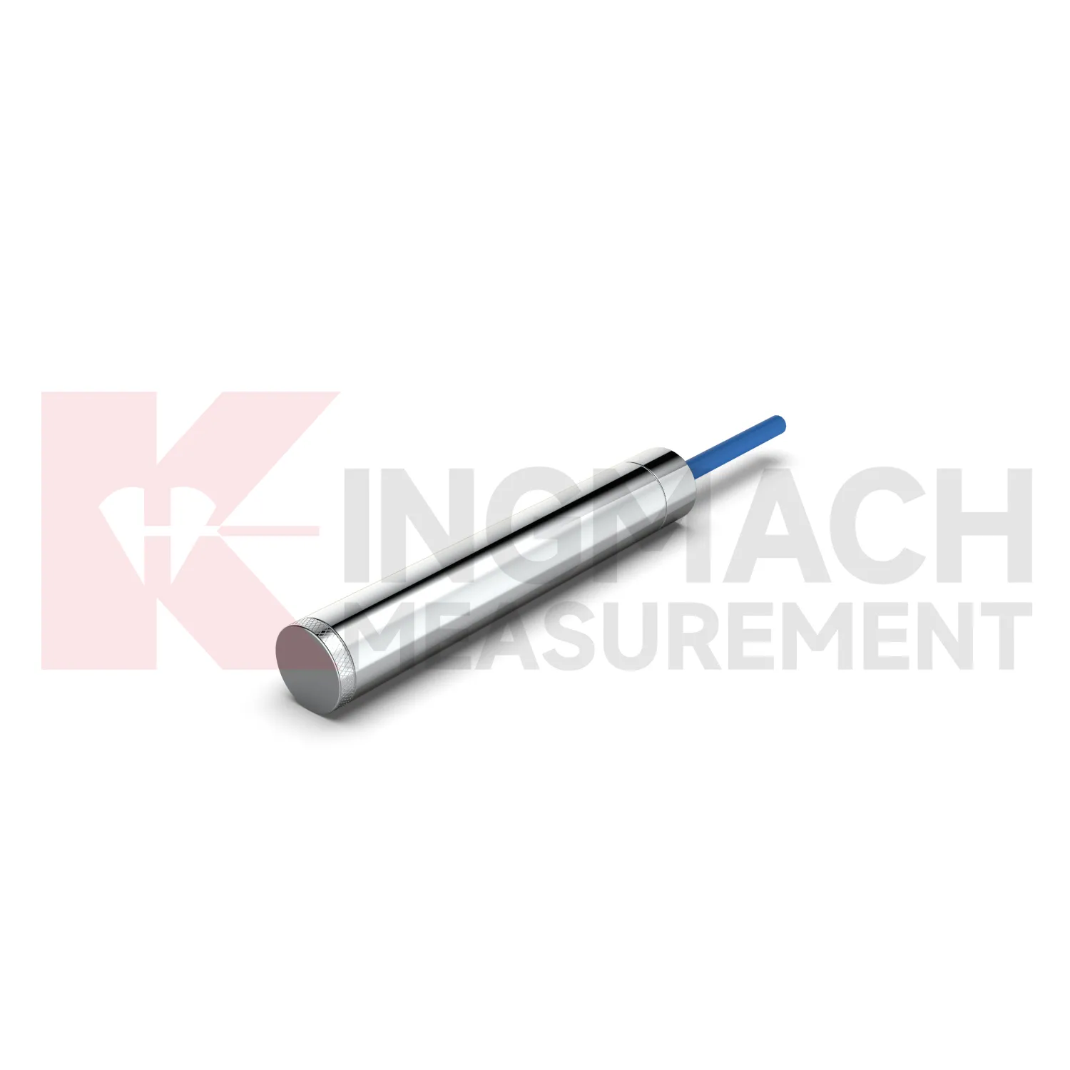
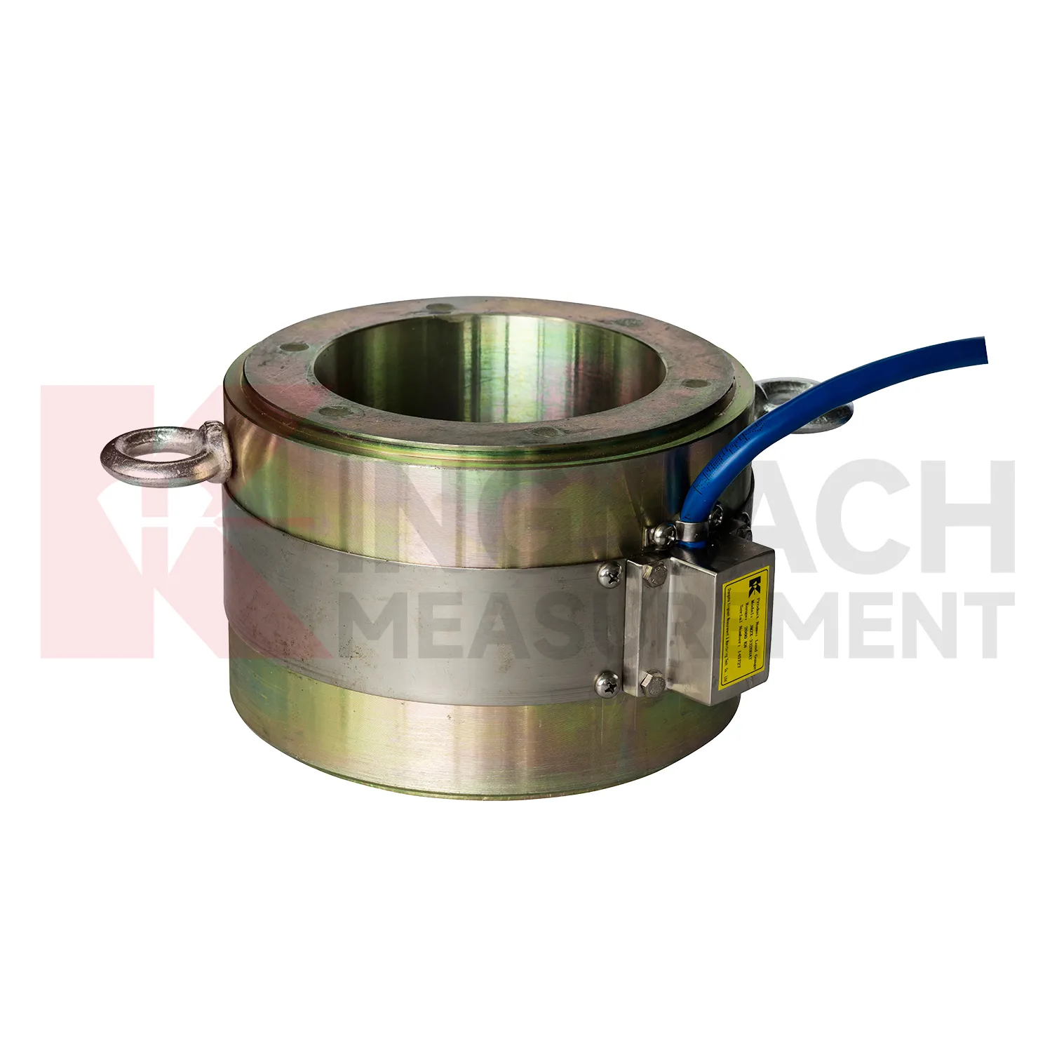
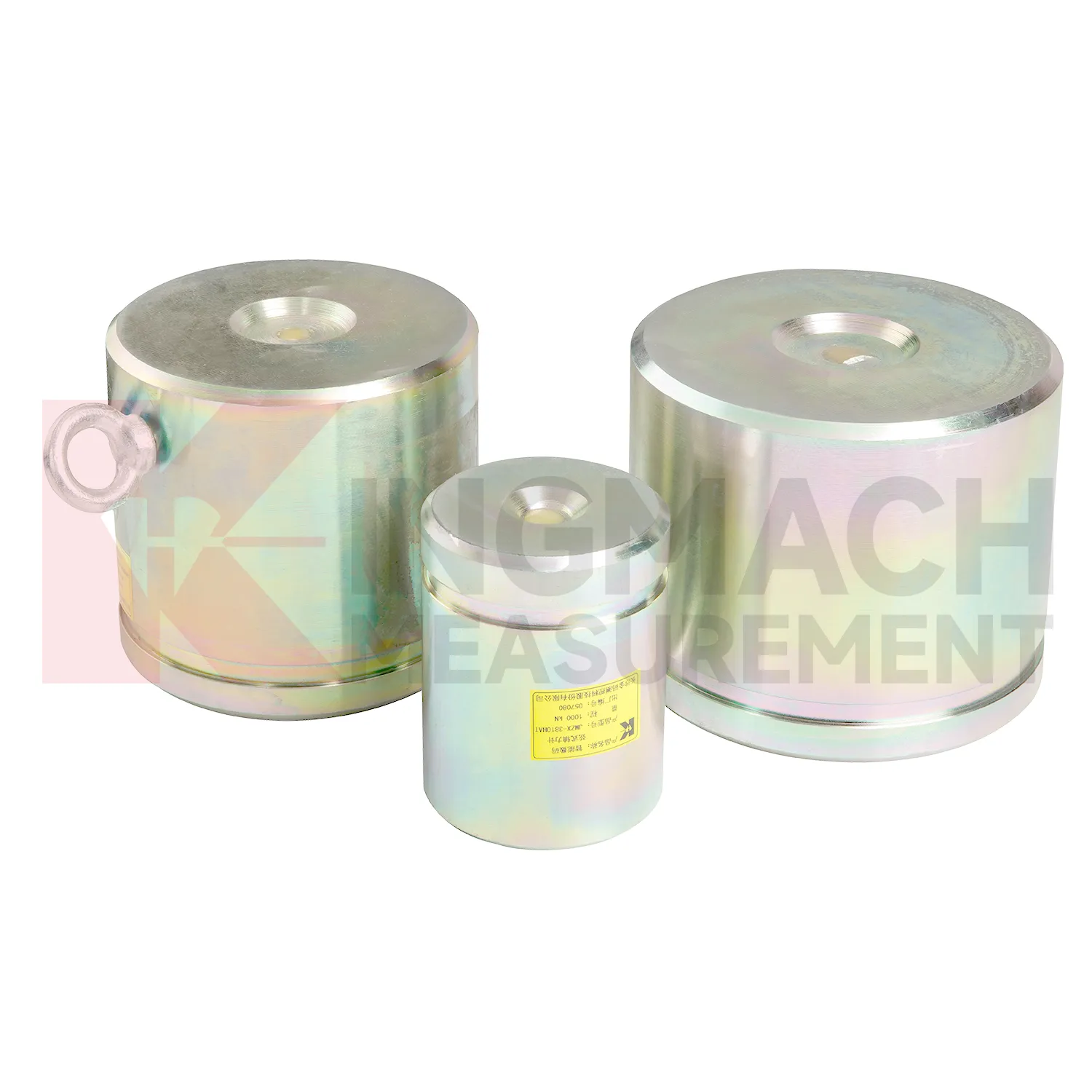
Kingmach load cell wire diagram products are built for projects that need force data with a clear technical trail. The hollow load cell JMZX-3XXXHAT uses an annular multi-string elastic steel structure and is listed from 500 kN to 8000 kN, with 0.1 kN sensitivity on the 500 kN model and 1 kN sensitivity on larger models. Its product file also lists a 50 year design life, digital output, automatic temperature correction, waterproof durability, and storage for 800 measurement records. Those details are relevant in bridge cable force monitoring, anchor testing, and long term structural health monitoring, where the same point may be checked for many years. Kingmach, based in Changsha, supplies sensors with readouts, data loggers, DTUs, and software platforms, so the measuring point can be connected to a wider monitoring network. For a project team, the important value is not a catalog claim. It is the ability to identify the sensor, read the same force channel consistently, compensate temperature influence, and keep a documented record when access becomes difficult after construction. For brand context, Kingmach Measurement & Monitoring Technology Co., Ltd. works from Changsha, Hunan, and its product pages group load sensing with structural health monitoring, engineering monitoring sensors, readouts, data loggers, instrumentation cables, and visualization software. That catalog context matters because a force sensor is often purchased with the equipment needed to read and archive it.
Application of load cell wire diagram
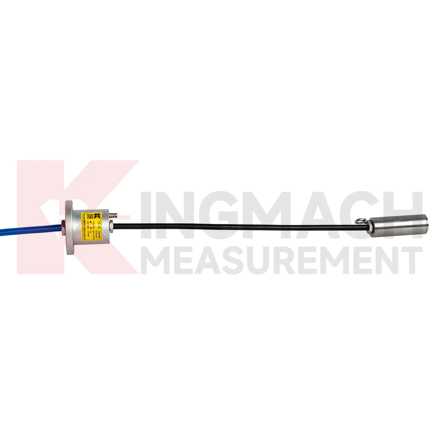
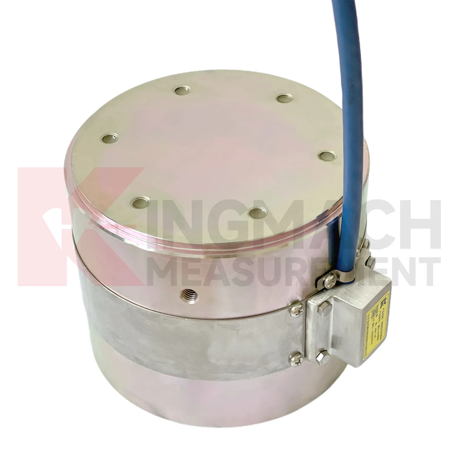
In tunnel engineering and underground works, load cell wire diagram is often placed on steel supports, temporary struts, surrounding rock pressure points, or contact zones near retaining elements. The main monitoring need is early detection of force change during excavation, lining work, grouting, groundwater fluctuation, or nearby construction. The JMZX-38XXHAT axial force load meter lists 200 kN to 3000 kN ranges, 0.1 kN or 1 kN sensitivity, 0.5%FS accuracy, direct kN display, and a 1 MPa waterproof rating. These parameters suit wet, crowded, and time sensitive underground sites. Where soil or contact pressure is the issue, earth pressure cells with 0.3 MPa to 8 MPa ranges and 0.001 MPa resolution can be added. The field problem is usually not a lack of readings, but knowing which reading belongs to which stage. Clear channel names, protected cables, and first stable readings after each excavation step help teams see whether the support system is loading normally or moving toward a risky pattern. For underground work, the first stable reading after each support stage should be kept with excavation depth, support time, and groundwater condition. That extra context helps explain whether a force change belongs to the structure, the soil, or the construction sequence.
The future of load cell wire diagram
Future load cell wire diagram design will keep moving toward lower maintenance without making the device harder to verify. Waterproof structures, high strength vibrating wires, automatic temperature correction, and smart chips already reduce field workload on Kingmach models. The next steps may include better connector sealing, self-diagnosis of signal quality, power efficient acquisition, and cleaner integration with cloud platforms. For remote dams, slopes, bridges, and rail corridors, LoRa, 4G, satellite, or wired hybrid systems may be selected according to access and power conditions. Long term data also needs stable units, channel names, calibration files, and inspection notes. Without those, a smart sensor can still produce a confusing record. Future procurement may therefore ask for sensor performance and data governance together: range, accuracy, service life, waterproof rating, memory, communication method, and exportable records. Kingmach's broad monitoring catalog is well positioned for this combined hardware and data requirement. Long life hardware still needs verifiable records around it.
Care & Maintenance of load cell wire diagram
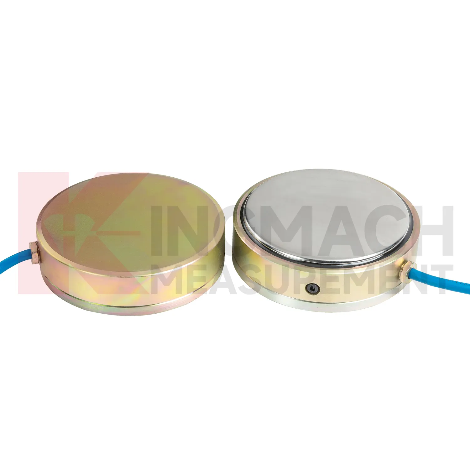
For load cell wire diagram installed in foundation pits or tunnels, the maintenance routine must fit a fast changing site. Axial force meters may cover 200 kN to 3000 kN with 0.5%FS accuracy and direct kN display, while earth pressure cells may cover 0.3 MPa to 8 MPa with 0.001 MPa resolution. During installation, confirm that steel support surfaces have enough thickness and strength, and add buffer plates where stress concentration is possible. Protect the sensor body and cable from equipment impact, cutting, concrete splash, and standing water. During excavation, check readings after each major stage rather than waiting for a fixed calendar date. If a channel becomes unstable, inspect the cable route, connector, readout, and temperature condition first. Long term points should have waterproof labels, photo records, and clear channel mapping. Sudden changes should be compared with wall movement, settlement, water pressure, and site work before any conclusion is recorded.
Kingmach load cell wire diagram
load cell wire diagram becomes most useful when the project treats it as part of a measurement chain. The chain starts with model selection and calibration, continues through surface preparation, installation, cable protection, readout setup, and first stable reading, then carries on through reporting and maintenance. Kingmach's range includes products with high capacity force measurement, waterproof construction, smart memory, direct kN display, and compatibility with readouts and automated acquisition systems. Those features only pay off when the field record is disciplined. The sensor should be named consistently, protected from mechanical damage, checked after loading events, and compared with nearby monitoring points. A force value that appears unusual should not be accepted or rejected in isolation. It should be checked against temperature, recent work, cable condition, connector sealing, and the last normal trend before a conclusion is made. That same record can later support warranty review, acceptance files, and maintenance planning. This is especially useful when the same point moves from construction control into long term asset monitoring.
FAQ
Q: What does load cell wire diagram do in a foundation pit or tunnel? A: It measures axial force in steel supports, anchor load, or pressure change as excavation and support stages progress. Q: Which Kingmach model fits steel support axial force? A: The JMZX-38XXHAT axial force meter is listed from 200 kN to 3000 kN, with 0.1 kN or 1 kN sensitivity and 0.5%FS accuracy. Q: Is it suitable for wet underground sites? A: The axial force meter lists a 1 MPa waterproof rating, but connector sealing and cable routing still need inspection. Q: Why is direct kN display useful? A: It reduces confusion because teams can read axial force directly instead of converting vibrating wire frequency on site. Q: What should trigger extra checks? A: Excavation step changes, rainfall, dewatering, support adjustment, sudden force jumps, or unstable channels.
Reviews
Ryan Lewis
Fast delivery and excellent product quality. The accelerometers and tiltmeters are highly reliable. Strongly recommend this company.
Daniel Brown
Excellent environmental monitoring sensors. The data is consistent, and the system integrates smoothly with our existing setup.
Latest Inquiries
To protect the privacy of our buyers, only public service email domains like Gmail, Yahoo, and MSN will be displayed. Additionally, only a limited portion of the inquiry content will be shown.
Amelia***@gmail.comSingapore
Hello, I am looking for visualization software for monitoring system data analysis. Please let me kn...
Mia***@gmail.comNetherlands
Dear team, we are interested in your readouts & data loggers compatible with multiple sensors. Do yo...